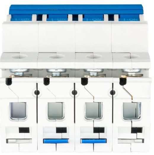
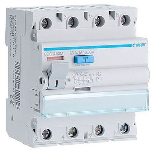
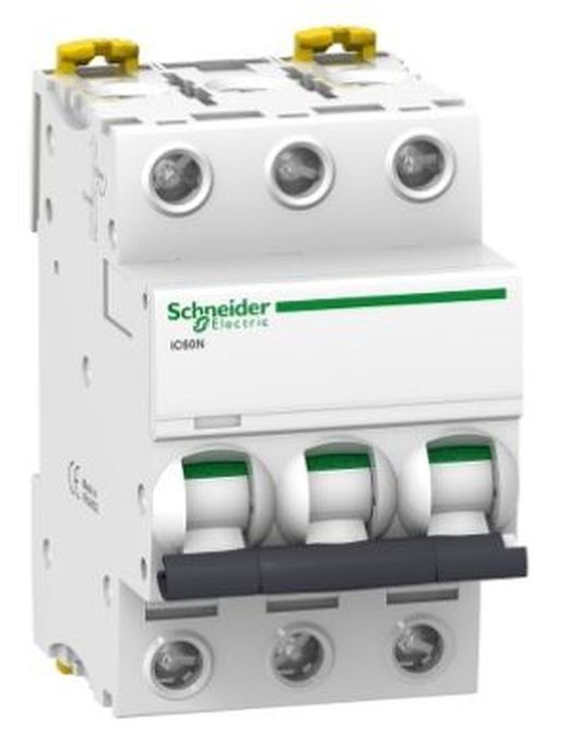
Automatic Magnetothermal Switch 3P+N Pls6-C40/3N 6Ka
Brand: Eaton
Reference: 243022
Description
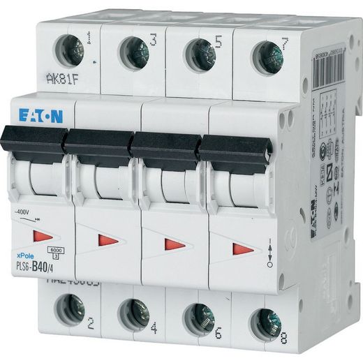
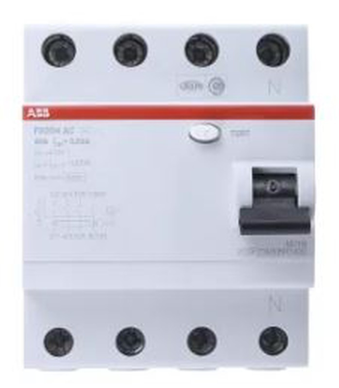
Automatic Magnetothermal Switch 3P+N Pls6-C40/3N 6Ka, Eaton series Moeller xPole - PLZ6/M MCB. PLS6, 3-pole+N, trip characteristic: C, rated current In: 40 A, rated switching capacity IEC/EN 60898-1: 6 kA
Details
3P+N Automatic Magnetothermal Switch Pls6-C40/3N 6Ka, Eaton series Moeller xPole - PLZ6/M MCB. PLS6, 3-pole+N, trip characteristic: C, rated current In: 40 A, rated switching capacity IEC/EN 60898-1: 6 kA
GENERAL SPECIFICATIONS
PRODUCT NAME
Eaton Moeller series xPole - PLS6/M MCB
PRODUCT LENGTH/DEPTH
85 mm
HEIGHT OF THE PRODUCT
73mm
PRODUCT WIDTH
70mm
WEIGHT OF THE PRODUCT
0.456 kg
CONFORMITY(S)
RoHS compliant
MODEL CODE
PLS6-C40/3N-MW
DELIVERY SCHEDULE
APPLICATION
Switchgear for residential and commercial applications
XPole - Switchgear for residential and commercial applications
NUMBER OF POLES
Tripolar + N
NUMBER OF POLES (TOTAL)
4
NUMBER OF POLES (PROTECTED)
3
SHOOTING CHARACTERISTICS
C
UNLOCKING FEATURE
C
NOMINAL AMPERAGE
40 A
TYPE
Magnetothermal automatic switch
PLS6
TECHNICAL DATA - ELECTRICAL
TYPE OF VOLTAGE
AC
NOMINAL OPERATING VOLTAGE (EU) - MAX.
400 V
ASSIGNED INSULATION VOLTAGE (UI)
440 V
ASSIGNED VOLTAGE SUPPORTED TO THE IMPULSE (UIMP)
4 kV
NOMINAL FREQUENCY (MIN.)
50 Hz
NOMINAL FREQUENCY (MAX.)
60 Hz
NOMINAL CUTTING CAPACITY (IEC/EN 60898-1)
6 kA
ASSIGNED SHORT CIRCUIT CUTTING CAPACITY (EN 60898) AT 230 V
6 kA
ASSIGNED SHORT CIRCUIT CUTTING CAPACITY (EN 60898) AT 400 V
6 kA
ASSIGNED SHORT CIRCUIT CUTTING CAPACITY (IEC 60947-2) AT 230 V
0 kA
RATED SHORT CIRCUIT CUTTING CAPACITY (IEC 60947-2) AT 400 V
0 kA
OVERVOLTAGE CATEGORY
III
DEGREE OF POLLUTION
2
TECHNICAL DATA - MECHANICAL
WIDTH IN SERIES OF MODULAR SPACING
4
INTEGRATED DEPTH
70.5mm
DEGREE OF PROTECTION
IP20
CONNECTABLE CONDUCTOR SECTION (RIGID CORE) - MIN.
1 mm²
CONNECTABLE CONDUCTOR SECTION (RIGID CORE) - MAX.
25 mm²
CONNECTABLE CONDUCTOR SECTION (MULTIFIRE) - MIN.
1 mm²
CONNECTABLE CONDUCTOR SECTION (MULTI-WIRE) - MAX.
25 mm²
DESIGN VERIFICATION ACCORDING TO THE IEC/EN 61439 STANDARD - TECHNICAL DATA
ASSIGNED USE CURRENT FOR SPECIFIC THERMAL DISSIPATION (INPUT)
40 A
THERMAL DISSIPATION PER POLE, DEPENDING ON THE CURRENT
0 W
THERMAL DISSIPATION OF THE EQUIPMENT, DEPENDENT ON THE CURRENT
11.5 W
STATIC THERMAL DISSIPATION, NOT DEPENDENT ON THE CURRENT
0 W
HEAT DISSIPATION CAPACITY
0 W
AMBIENT OPERATING TEMPERATURE - MIN.
-25 °C
AMBIENT OPERATING TEMPERATURE - MAX.
75 °C
DESIGN VERIFICATION ACCORDING TO THE IEC/EN 61439 STANDARD
10.2.2 CORROSION RESISTANCE
Meets the requirements of the product standard.
10.2.3.1 VERIFICATION OF THE THERMAL STABILITY OF THE CABINETS
Meets the requirements of the product standard.
10.2.3.2 VERIFICATION. RESISTANCE OF INSULATING MATERIALS IN CONDITION. NORMAL HEAT
Complies with the requirements of the product standard.
10.2.3.3. BEEF. MAT. AISL. TO EXCESSIVE HEAT/FIRE DUE TO THE EFFECT. INTERNAL
Complies with the requirements of the product standard.
10.2.4 RESISTANCE TO ULTRAVIOLET RADIATION (UV)
Meets the requirements of the product standard.
10.2.5 ELEVATION
Not applicable, since it is necessary to evaluate all the switchgear.
10.2.6 MECHANICAL IMPACT
Not applicable, since it is necessary to evaluate all the switchgear.
10.2.7 REGISTRATIONS
Meets the requirements of the product standard.
10.3 DEGREE OF PROTECTION OF ASSEMBLY
Not applicable, since it is necessary to evaluate all the switchgear.
10.4 EFFLUVIOUS DISTANCES AND CLEARANCES
Complies with the requirements of the product standard.
10.5 PROTECTION AGAINST ELECTRIC SHOCK
Not applicable, since it is necessary to evaluate all the switchgear.
10.6 INCORPORATION OF SWITCHING DEVICES AND COMPONENTS
Not applicable, since it is necessary to evaluate all the switchgear.
10.7 INTERNAL ELECTRICAL CONNECTIONS AND CIRCUITS
It is the responsibility of the panel builder.
10.8 EXTERNAL CONDUCTOR CONNECTIONS
It is the responsibility of the panel builder.
10.9.2 SUPPLY FREQUENCY ELECTRICAL RESISTANCE
It is the responsibility of the panel builder.
10.9.3 SUPPORTED IMPULSE VOLTAGE
It is the responsibility of the panel builder.
10.9.4 TESTING CABINETS MADE OF INSULATING MATERIAL
It is the responsibility of the panel builder.
10.10 INCREASE IN TEMPERATURE
The panel builder is responsible for calculating the temperature increase. Eaton will provide heat dissipation data for the devices.
10.11 RESISTANCE TO SHORT CIRCUITS
It is the responsibility of the panel builder. Switchgear specifications must be taken into account.
10.12 ELECTROMAGNETIC COMPATIBILITY
It is the responsibility of the panel builder. Switchgear specifications must be taken into account.
10.13 MECHANICAL FUNCTION
The device meets the requirements, as long as the information in the instruction booklet (IL) is respected.
ADDITIONAL INFORMATION
CURRENT LIMITATION CLASS
3
CHARACTERISTICS
Simultaneous N-neutral switching
Possible additional equipment
SPECIAL FEATURES
Ambient temperature indication: An increase of 1°C results in a linear reduction of 0.5% of the allowable current load
USED WITH
PLS6
Magnetothermal automatic switch
